/******************************************************************************
PIR_Motion_Detector_Example.ino
Example sketch for SparkFun's PIR Motion Detector
(https://www.sparkfun.com/products/13285)
Jim Lindblom @ SparkFun Electronics
May 2, 2016
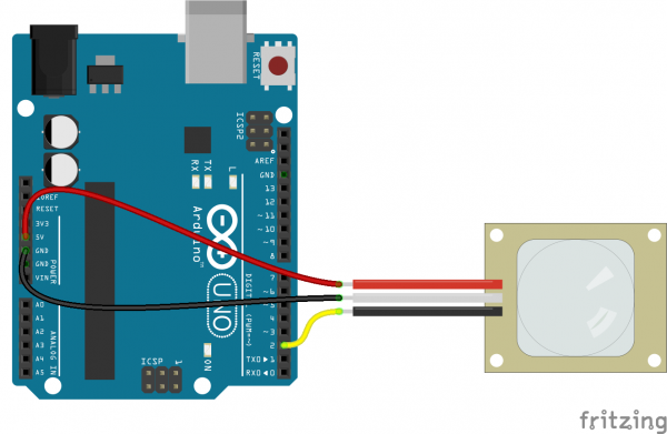
The PIR motion sensor has a three-pin JST connector terminating it. Connect
the wire colors like this:
- Black: D2 - signal output (pulled up internally)
- White: GND
- Red: 5V
Connect an LED to pin 13 (if your Arduino doesn't already have an LED there).
Whenever the PIR sensor detects movement, it'll write the alarm pin LOW.
Development environment specifics:
Arduino 1.6.7
******************************************************************************/constint MOTION_PIN =2; // Pin connected to motion detectorconstint LED_PIN =13; // LED pin - active-highvoidsetup()
{
Serial.begin(9600);
// The PIR sensor's output signal is an open-collector, // so a pull-up resistor is required:pinMode(MOTION_PIN, INPUT_PULLUP);
pinMode(LED_PIN, OUTPUT);
}
voidloop()
{
int proximity =digitalRead(MOTION_PIN);
if (proximity == LOW) // If the sensor's output goes low, motion is detected
{
digitalWrite(LED_PIN, HIGH);
Serial.println("Motion detected!");
}
else
{
digitalWrite(LED_PIN, LOW);
}
}
Description: This is a simple to use motion sensor. Power it up and wait 1-2 seconds for the sensor to get a snapshot of the still room. If anything moves after that period, the ‘alarm’ pin will go low.
This unit works great from 5 to 12V (datasheet shows 12V). You can also install a jumper wire past the 5V regulator on board to make this unit work at 3.3V. Sensor uses 1.6mA@3.3V.
The alarm pin is an open collector meaning you will need a pull up resistor on the alarm pin. The open drain setup allows multiple motion sensors to be connected on a single input pin. If any of the motion sensors go off, the input pin will be pulled low.
We’ve finally updated the connector! Gone is the old “odd” connector, now you will find a common 3-pin JST! This makes the PIR Sensor much more accessible for whatever your project may need. Red = Power, White = Ground, and Black = Alarm.