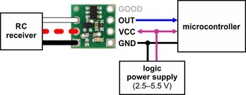
본 제품은 RC 리시버 (RC Receiver)로부터 신호를 받아서, 릴레이, LED, MOSFET 등을 스위칭할 수 있는 모듈입니다.
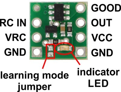
위의 핀들 중, 왼쪽의 세 핀은 RC 리시버에서 받고, 오른족의 핀들 중 GOOD은 무선 신호의 상태가 좋은지 피드백을 줍니다. 그리고, OUT핀을 통해서 마이크로컨트롤러, MOSFET, LED, 릴레이 등을 제어하게 됩니다.
The Pololu RC Switch with Digital Output has 7 through holes spaced 0.1″ apart that fit 0.1″ header pins.
RC interface
The GND, VRC, and RC IN pins make up the switch’s RC interface and can be connected directly to an RC receiver or servo controller:
- The GND pin is the ground or reference voltage.
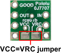
- The VRC pin connects to the RC power line. The power from VRC is not used by default, but a jumper on the bottom of the board can be bridged with solder to power the board from VRC.
- The RC IN pin is the RC signal input. The switch measures the width of pulses on this line and uses that to decide whether to activate or not.
Power
The VCC pin powers the basic functions of the board and needs to be connected to a power source between 2.5 V and 5.5 V. The VCC=VRC jumper on the bottom of the board can be bridged with solder to power the board from VRC or to pass power from VCC to the RC receiver.
Outputs and indicator LED
The RC switch provides feedback about what state it is in via a yellow indicator LED. The LED behavior is described in Section 8. Status information is also provided by two outputs:
- The GOOD pin indicates the presence of a valid RC signal (10–330 Hz pulse rate, 0.5–2.5 ms pulse width).
- The OUT pin indicates whether the switch is active.
When these outputs are high they will be at the same voltage level as VCC. When low, these outputs will be at 0 V (ground). These outputs do not have resistors in series with them. Each output can source or sink up to 25 mA.